
Welding Symbols Chart: AWS and ISO Weld Symbol Table (Free PDF)
How to read AWS A2.4 welding symbols: arrow side, fillet and groove shapes, supplementary symbols, dimension positions and ISO 2553 differences. Free PDF, PNG and CSV.
Welding Symbol Anatomy: Reference Line, Arrow, Tail and Sides (AWS A2.4)

| Element | Shape on the drawing | Where it sits | What it tells the welder | Common mistake |
|---|---|---|---|---|
| Reference line | Straight horizontal line | Centre of the welding symbol, always horizontal | Carries every weld symbol and dimension, read left to right | Drawing it sloped or treating it as an ordinary leader line |
| Arrow | Leader line ending in an arrowhead | Leaves one end of the reference line and touches the joint | Identifies the joint; the side the arrowhead touches is the arrow side | Thinking the arrow points at the finished weld face |
| Arrow side | Weld symbol drawn below the reference line | Below the line | Weld goes on the side of the joint the arrowhead touches | Swapping sides when the arrow points upward or leaves the left end |
| Other side | Weld symbol drawn above the reference line | Above the line | Weld goes on the side of the joint opposite the arrowhead | Reading 'above the line' as 'top of the part' |
| Both sides | Weld symbols mirrored above and below the line | Both sides of the line | Weld on both sides of the joint; each side can carry its own size | Assuming one size covers both sides when only one side is dimensioned |
| No side significance | Weld symbol centred across the line | Straddling the reference line | Side does not matter; used only for spot, projection, seam and square-groove symbols | Using a centred symbol for fillet or bevel welds, which always need a side |
| Break in arrow | Arrow leader with a jog in it | In the arrow leader line | The arrow points at the member that gets the edge preparation (bevel, J, flare-bevel) | Ignoring the break and preparing the wrong plate |
| Tail | Two short lines forming an open V | End of the reference line away from the arrow | Holds process, specification, procedure or other notes, e.g. GMAW or a WPS number | Looking for sizes there; the tail is left off when no note is needed |
| Weld symbol | Shape for the weld type (fillet triangle, groove shapes, circle, etc.) | On or across the reference line, inside its length | Type of weld to make | Confusing the weld symbol (one shape) with the welding symbol (the whole assembly) |
| Weld-all-around | Small open circle | At the arrow and reference line junction | Weld continues all the way around the joint | Welding only the face the arrow touches on a tube-to-plate joint |
| Field weld | Small flag on a short staff | At the arrow and reference line junction | Weld is made on site during erection, not in the shop | Missing an old-style filled black circle that meant the same thing |
| Multiple reference lines | Two or more stacked reference lines on one arrow | Stacked on the same arrow | Order of operations: the line nearest the arrow is done first | Reading the top line as the first operation |
| Reversed symbol | Arrow on the left, tail on the right | Whole symbol mirrored | Size still reads on the left and length on the right of the weld symbol | Reversing the size and length order along with the arrow |
Arrow side below and other side above applies to AWS A2.4 and ISO 2553 System B; ISO System A uses a dashed line instead (see the AWS vs ISO table).
If you’ll read this table as if it’s a weld symbol on a piece of print, finding the arrow first, then the reference line, then checking which side of that line the weld symbol is on, and finally looking at the tail, you’ll see that each row is an element named, shown, located and described. Each row also identifies the mistake shops makes most often with it.
Column 1 is the “Element” from the training and drawings. Column 2 is the plain word description of what shape is being drawn. Column 3 is where it sits on the symbol. Column 4 is the instruction to the welder. Column 5 is the misread that you should of check for.
But the biggest rule is for the AWS system. The direction of the arrow do not determine the side. The reference line sets the side.
Regardless of which direction the arrow points, a symbol above the line indicates an other-side weld, and a symbol below the line indicates an arrow-side weld. And again, the arrow just selects the joint. It determines the arrow side by selecting the face it touches.
Arrow, This indicates a break in the arrow applies to certain welds. This applies to groove types such as J, bevel, flare-bevel, etc, where one of the members have been prepared but the other hasn’t. The arrow is pointing to which member needs to be prepared. In the absence of a break, it was either clear who should prepare what or up to the fabricator.
Where the arrow intersects with the reference line is where the circle and flag are located. The circle indicates a weld all the way around. This is something you may not notice on a bracket or tube.
A flag indicates a field weld. No flag indicates a shop weld. On older drawings, a field weld may be indicated by a filled in black dot at the elbow.
The table shows the AWS A2.4 layout for North America. That’s the one you’ll see most often here.
It also applies to ISO 2553 System B, reading as shown. In ISO 2553 System A there is an additional dashed line parallel with the reference line. In this case the dashed line sets the side. Check the final table before using the above and below rule on an ISO or European drawing.
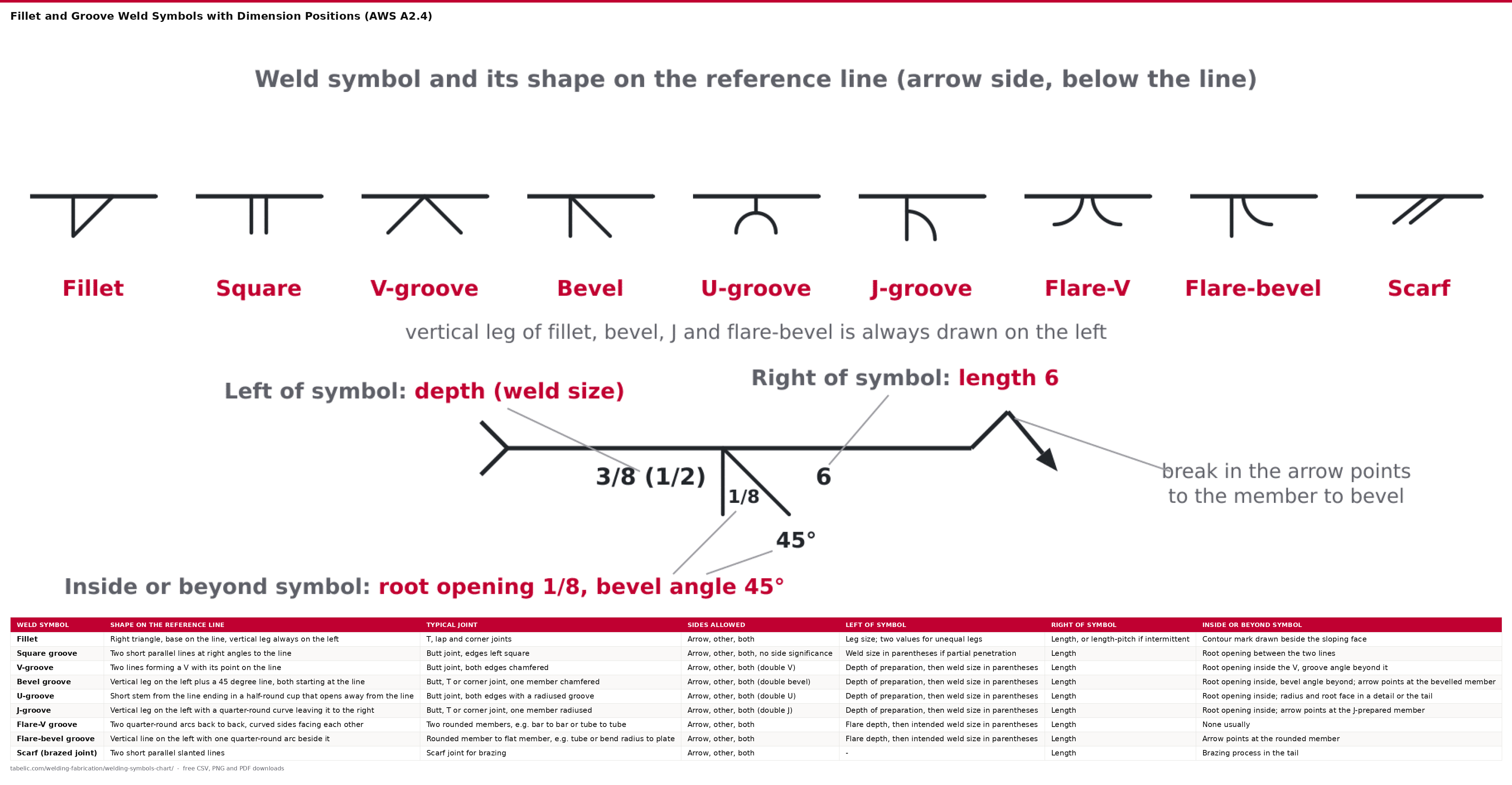
Fillet and Groove Weld Symbols with Dimension Positions (AWS A2.4)

| Weld symbol | Shape on the reference line | Typical joint | Sides allowed | Left of symbol | Right of symbol | Inside or beyond symbol |
|---|---|---|---|---|---|---|
| Fillet | Right triangle, base on the line, vertical leg always on the left | T, lap and corner joints | Arrow, other, both | Leg size; two values for unequal legs | Length, or length-pitch if intermittent | Contour mark drawn beside the sloping face |
| Square groove | Two short parallel lines at right angles to the line | Butt joint, edges left square | Arrow, other, both, no side significance | Weld size in parentheses if partial penetration | Length | Root opening between the two lines |
| V-groove | Two lines forming a V with its point on the line | Butt joint, both edges chamfered | Arrow, other, both (double V) | Depth of preparation, then weld size in parentheses | Length | Root opening inside the V, groove angle beyond it |
| Bevel groove | Vertical leg on the left plus a 45 degree line, both starting at the line | Butt, T or corner joint, one member chamfered | Arrow, other, both (double bevel) | Depth of preparation, then weld size in parentheses | Length | Root opening inside, bevel angle beyond; arrow points at the bevelled member |
| U-groove | Short stem from the line ending in a half-round cup that opens away from the line | Butt joint, both edges with a radiused groove | Arrow, other, both (double U) | Depth of preparation, then weld size in parentheses | Length | Root opening inside; radius and root face in a detail or the tail |
| J-groove | Vertical leg on the left with a quarter-round curve leaving it to the right | Butt, T or corner joint, one member radiused | Arrow, other, both (double J) | Depth of preparation, then weld size in parentheses | Length | Root opening inside; arrow points at the J-prepared member |
| Flare-V groove | Two quarter-round arcs back to back, curved sides facing each other | Two rounded members, e.g. bar to bar or tube to tube | Arrow, other, both | Flare depth, then intended weld size in parentheses | Length | None usually |
| Flare-bevel groove | Vertical line on the left with one quarter-round arc beside it | Rounded member to flat member, e.g. tube or bend radius to plate | Arrow, other, both | Flare depth, then intended weld size in parentheses | Length | Arrow points at the rounded member |
| Scarf (brazed joint) | Two short parallel slanted lines | Scarf joint for brazing | Arrow, other, both | - | Length | Brazing process in the tail |
Shapes are the arrow-side form; the other-side form is the same shape mirrored above the line. A single groove with no size is complete joint penetration unless the drawing says otherwise.
Find the shape on the reference line in the second column to name the weld, then use the last three columns to see where its numbers lives. Each of these symbols is drawn as it would appear on the arrow side of the line (below the line). For an other-side weld, you mirror the same shape above the line; a double groove indicate the weld on both sides.
The weld symbol give the type of weld; the shape on the reference line indicate how it's drawn. Sides allowed lists where the symbol can be positioned, and the typical joint tell you where the parts meet.
Place sizes to the left of the symbol. For a groove, this is the depth of prep plus the weld size in parentheses; for a fillet, it is the leg size. Place lengths and pitch to the right of the symbol. Place the groove angle outside, farther from the line. Place the root opening nearest or inside the line.
The two shapes don’t change no matter which end the arrow comes out. The flare-bevel, J, bevel, and fillet triangle is all drawn with the vertical leg on the left side. But that doesn’t refer to the vertical member of the joint, so what do you look for? The arrow tell you which member will get prepped, and where there’s a break in the arrow, that’s where it matters.
Avoid these common traps: The angle on one member alone is called the bevel angle, but remember the full included angle between two prepared faces is the V-groove angle. A 60 degree V equals two 30 degree bevels.
Groove depth and groove weld size are not the same thing, and the larger size go in parentheses if the weld is expected to penetrate deeper than the preparation. Single groove symbol without size is read as complete joint penetration, and never make a groove weld smaller than its depth of preparation.
You would of expect a tail note, or at least a section detail for U and J grooves as they require a root face and radius that this symbol cannot illustrate. Tube, rebar, and sheet metal frequently have a significant corner radius and use flare grooves; here the flare depth is given with the desired effective size in parentheses.
You notice that it doesn't include resistance, back, edge, seam, spot, surfacing, stud, and plug welds; those are in the next table. It does show the AWS symbol shapes.
Similar shapes are used in ISO 2553 except that there are additional symbols for certain prepared edges, which is why you check against the standard referenced in the drawing’s title block.
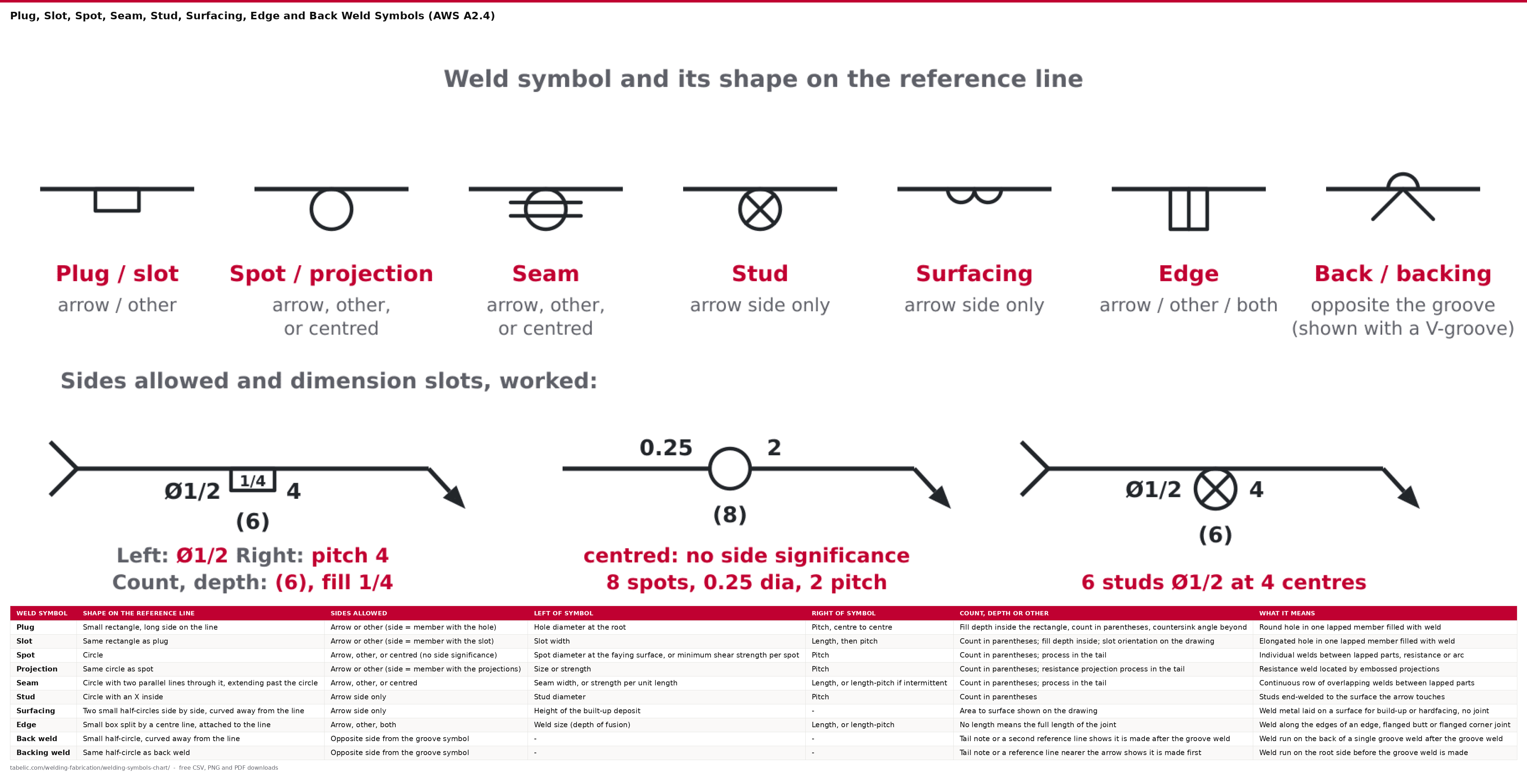
Plug, Slot, Spot, Seam, Stud, Surfacing, Edge and Back Weld Symbols (AWS A2.4)

| Weld symbol | Shape on the reference line | Sides allowed | Left of symbol | Right of symbol | Count, depth or other | What it means |
|---|---|---|---|---|---|---|
| Plug | Small rectangle, long side on the line | Arrow or other (side = member with the hole) | Hole diameter at the root | Pitch, centre to centre | Fill depth inside the rectangle, count in parentheses, countersink angle beyond | Round hole in one lapped member filled with weld |
| Slot | Same rectangle as plug | Arrow or other (side = member with the slot) | Slot width | Length, then pitch | Count in parentheses; fill depth inside; slot orientation on the drawing | Elongated hole in one lapped member filled with weld |
| Spot | Circle | Arrow, other, or centred (no side significance) | Spot diameter at the faying surface, or minimum shear strength per spot | Pitch | Count in parentheses; process in the tail | Individual welds between lapped parts, resistance or arc |
| Projection | Same circle as spot | Arrow or other (side = member with the projections) | Size or strength | Pitch | Count in parentheses; resistance projection process in the tail | Resistance weld located by embossed projections |
| Seam | Circle with two parallel lines through it, extending past the circle | Arrow, other, or centred | Seam width, or strength per unit length | Length, or length-pitch if intermittent | Count in parentheses; process in the tail | Continuous row of overlapping welds between lapped parts |
| Stud | Circle with an X inside | Arrow side only | Stud diameter | Pitch | Count in parentheses | Studs end-welded to the surface the arrow touches |
| Surfacing | Two small half-circles side by side, curved away from the line | Arrow side only | Height of the built-up deposit | - | Area to surface shown on the drawing | Weld metal laid on a surface for build-up or hardfacing, no joint |
| Edge | Small box split by a centre line, attached to the line | Arrow, other, both | Weld size (depth of fusion) | Length, or length-pitch | No length means the full length of the joint | Weld along the edges of an edge, flanged butt or flanged corner joint |
| Back weld | Small half-circle, curved away from the line | Opposite side from the groove symbol | - | - | Tail note or a second reference line shows it is made after the groove weld | Weld run on the back of a single groove weld after the groove weld |
| Backing weld | Same half-circle as back weld | Opposite side from the groove symbol | - | - | Tail note or a reference line nearer the arrow shows it is made first | Weld run on the root side before the groove weld is made |
Plug and slot share one symbol, as do spot and projection, and back and backing weld; the dimensions, tail note or line sequence tell them apart.
For all of the weld symbols but a groove or a fillet, use this table. Match the shape, check that it fits into one of the allowed positions, and read the size on the left. Look to the right for the pitch. Look down the sixth column for any note, depth, or count.
The weld symbol tell you what kind of weld. The shape on the reference line defines the mark. The sides allowed column identifies where the symbol can be drawn. For plug, slot, and projection welds, the side indicates which member contains the projection or hole.
The left of symbol column gives height, width, diameter, strength, etc. The right of symbol column gives the pitch, or the length and pitch. The count, depth, or other column list the rest. These is things like the fill depth of a plug or the number of welds (in parentheses). The what it means column explain the finished weld.
This is where misread occurs because they share several symbols.
A rectangle is used for a plug and slot weld. To determine which one, look at the number on the left. If there’s a diameter on the left, then it’s a plug weld. If it’s width plus length, then it’s a slot weld.
A circle is used for spot and projection welds. To determine which one, you need to see what’s in the tail. That will tell you the process that was used.
Back and backing welds both use the half-circle. The difference is how they’re done. The order of operations is all that matters. And you’ll either see that in a stacked reference line or in a tail note. The line closest to the arrow are performed first.
For example, the size of a spot weld might be replaced with a strength requirement. Use minimum shear strength per spot for spot welds. Strength per unit length for seam welds. The strength is given in lbf or N. Strength value is a test requirement. It is not a dimension to measure on the part.
Stud and surfacing symbols is used on the arrow side only. Why? Because there isn't an "other side" of a surface deposit, or a stud.
Inside the rectangle, record the depth the plug fills. If it's a blank rectangle, fill the hole all the way.
The table above doesn’t include symbols for consumable inserts, spacers and backing strips. Those are additional symbols. Drawn opposite than a groove weld. In the following table. Followed by the rectangle-with-R. Backing is removed, this symbol marks it.
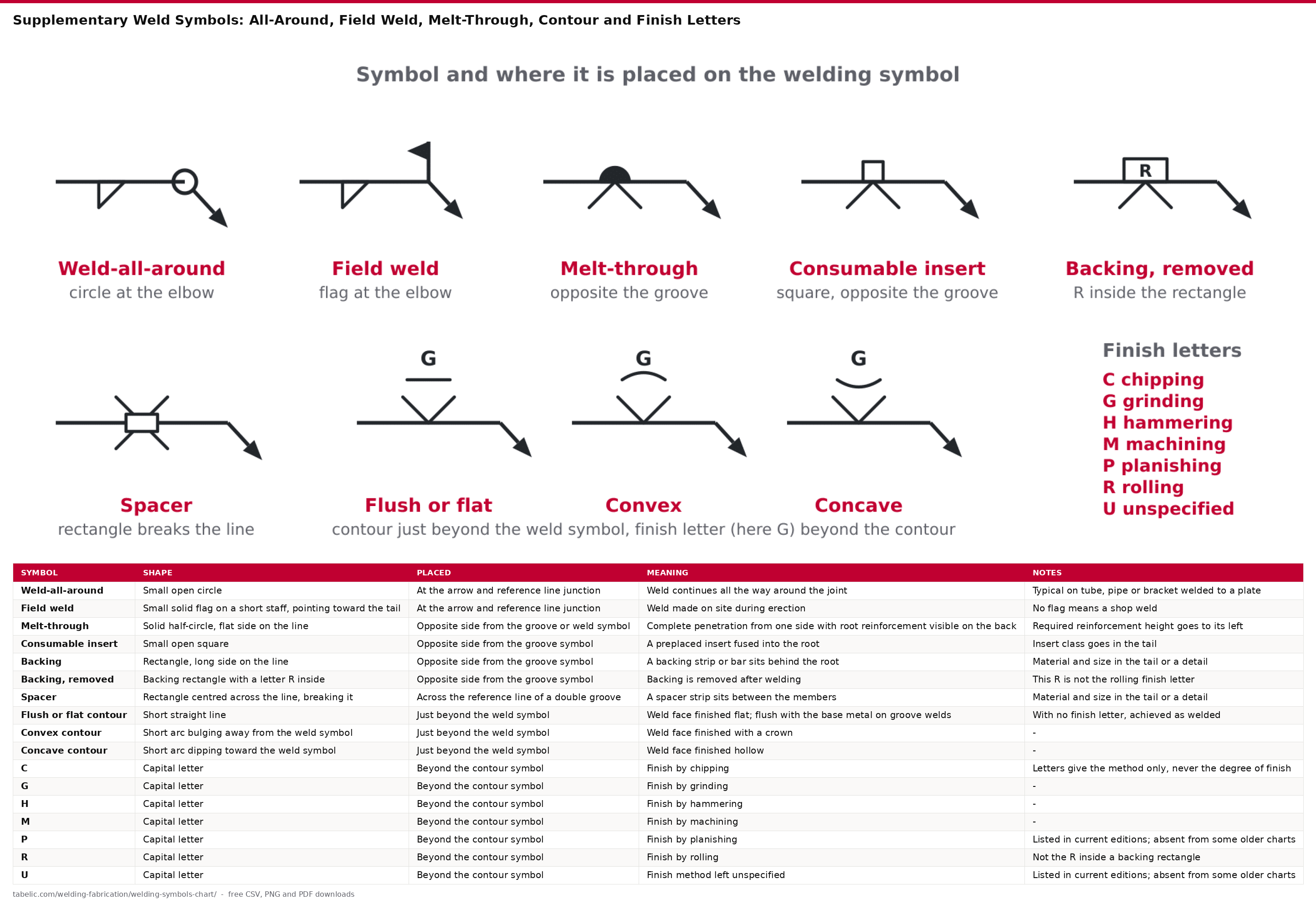
Supplementary Weld Symbols: All-Around, Field Weld, Melt-Through, Contour and Finish Letters

| Symbol | Shape | Placed | Meaning | Notes |
|---|---|---|---|---|
| Weld-all-around | Small open circle | At the arrow and reference line junction | Weld continues all the way around the joint | Typical on tube, pipe or bracket welded to a plate |
| Field weld | Small solid flag on a short staff, pointing toward the tail | At the arrow and reference line junction | Weld made on site during erection | No flag means a shop weld |
| Melt-through | Solid half-circle, flat side on the line | Opposite side from the groove or weld symbol | Complete penetration from one side with root reinforcement visible on the back | Required reinforcement height goes to its left |
| Consumable insert | Small open square | Opposite side from the groove symbol | A preplaced insert fused into the root | Insert class goes in the tail |
| Backing | Rectangle, long side on the line | Opposite side from the groove symbol | A backing strip or bar sits behind the root | Material and size in the tail or a detail |
| Backing, removed | Backing rectangle with a letter R inside | Opposite side from the groove symbol | Backing is removed after welding | This R is not the rolling finish letter |
| Spacer | Rectangle centred across the line, breaking it | Across the reference line of a double groove | A spacer strip sits between the members | Material and size in the tail or a detail |
| Flush or flat contour | Short straight line | Just beyond the weld symbol | Weld face finished flat; flush with the base metal on groove welds | With no finish letter, achieved as welded |
| Convex contour | Short arc bulging away from the weld symbol | Just beyond the weld symbol | Weld face finished with a crown | - |
| Concave contour | Short arc dipping toward the weld symbol | Just beyond the weld symbol | Weld face finished hollow | - |
| C | Capital letter | Beyond the contour symbol | Finish by chipping | Letters give the method only, never the degree of finish |
| G | Capital letter | Beyond the contour symbol | Finish by grinding | - |
| H | Capital letter | Beyond the contour symbol | Finish by hammering | - |
| M | Capital letter | Beyond the contour symbol | Finish by machining | - |
| P | Capital letter | Beyond the contour symbol | Finish by planishing | Listed in current editions; absent from some older charts |
| R | Capital letter | Beyond the contour symbol | Finish by rolling | Not the R inside a backing rectangle |
| U | Capital letter | Beyond the contour symbol | Finish method left unspecified | Listed in current editions; absent from some older charts |
Supplementary symbols add to a weld symbol; they never replace it. Letters C, G, H, M and R are long-standing; P and U appear in later references.
Once you’ve found the weld itself then you can follow through with this table. It’s a list of each of the marks that change the weld. These are the marks that tell you how far round to weld, where the weld is going to be, what the face needs to look like, and what is behind the root. Symbol, name. Shape, description. Placed, position. Meaning, instruction. Notes, easily missed detail.
You can see where they draw the symbols for the field weld flag and the all around circle. They’re not on the weld side of the arrow. Because they’re on the elbow they are applied to the entire symbol.
On the other side of the reference line from the groove symbol are the symbols for a spacer, backing, melt through, and consumable insert. These tells you what occurs on the root side of that groove.
Finish and contour are companions. Contour describes the shape; finish tells you how to get it. It's a drawing outside of the weld symbol.
When on a groove, the mark run parallel to the reference line. Beside a fillet, it is located next to the sloped side of the fillet.
Beyond the contour is a letter indicating how to achieve this shape. No letter on the contour indicates that the shape must be achieved as welded, without dressing. Weld is not dressed.
Now for the letter R: If it’s in a backing rectangle, that means remove the backing after welding. If it’s a finish letter outside of a contour, then that means rolling.
Finish letters indicates the process, but not the surface roughness. Surface textures require their own callout. A numeric finish require a separate surface texture callout.
For decades there has been a set of finish letters in the AWS system: C, G, H, M, and R. The letters stands for chipping, grinding, hammering, machining, and rolling respectively.
Additional references include P for planishing and U for unspecified added later. It's not an error if an older drawing doesn't use either of those. Surface finish is normaly stated using ordinary drawing symbols on ISO 2553 drawings.
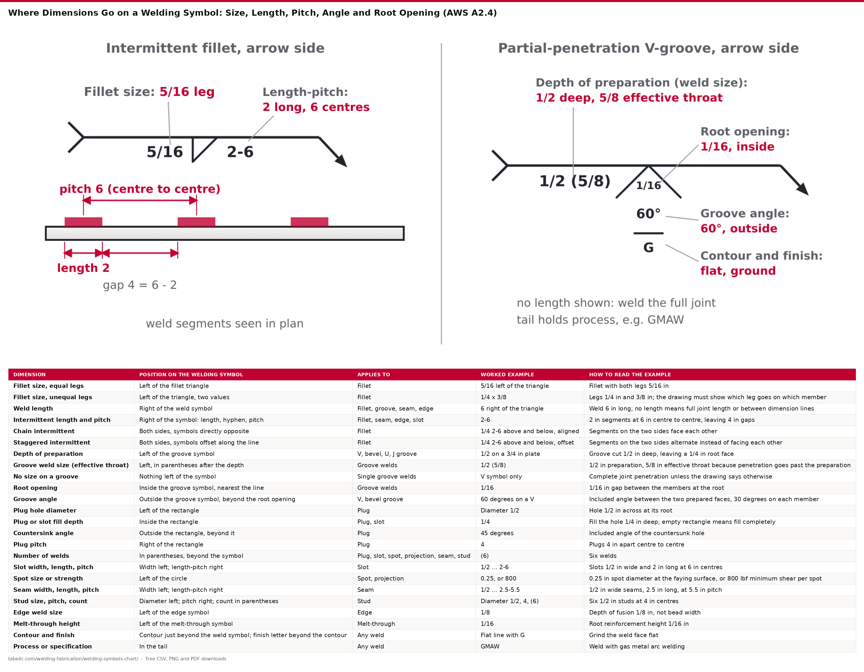
Where Dimensions Go on a Welding Symbol: Size, Length, Pitch, Angle and Root Opening (AWS A2.4)

| Dimension | Position on the welding symbol | Applies to | Worked example | How to read the example |
|---|---|---|---|---|
| Fillet size, equal legs | Left of the fillet triangle | Fillet | 5/16 left of the triangle | Fillet with both legs 5/16 in |
| Fillet size, unequal legs | Left of the triangle, two values | Fillet | 1/4 x 3/8 | Legs 1/4 in and 3/8 in; the drawing must show which leg goes on which member |
| Weld length | Right of the weld symbol | Fillet, groove, seam, edge | 6 right of the triangle | Weld 6 in long; no length means full joint length or between dimension lines |
| Intermittent length and pitch | Right of the symbol: length, hyphen, pitch | Fillet, seam, edge, slot | 2-6 | 2 in segments at 6 in centre to centre, leaving 4 in gaps |
| Chain intermittent | Both sides, symbols directly opposite | Fillet | 1/4 2-6 above and below, aligned | Segments on the two sides face each other |
| Staggered intermittent | Both sides, symbols offset along the line | Fillet | 1/4 2-6 above and below, offset | Segments on the two sides alternate instead of facing each other |
| Depth of preparation | Left of the groove symbol | V, bevel, U, J groove | 1/2 on a 3/4 in plate | Groove cut 1/2 in deep, leaving a 1/4 in root face |
| Groove weld size (effective throat) | Left, in parentheses after the depth | Groove welds | 1/2 (5/8) | 1/2 in preparation, 5/8 in effective throat because penetration goes past the preparation |
| No size on a groove | Nothing left of the symbol | Single groove welds | V symbol only | Complete joint penetration unless the drawing says otherwise |
| Root opening | Inside the groove symbol, nearest the line | Groove welds | 1/16 | 1/16 in gap between the members at the root |
| Groove angle | Outside the groove symbol, beyond the root opening | V, bevel groove | 60 degrees on a V | Included angle between the two prepared faces, 30 degrees on each member |
| Plug hole diameter | Left of the rectangle | Plug | Diameter 1/2 | Hole 1/2 in across at its root |
| Plug or slot fill depth | Inside the rectangle | Plug, slot | 1/4 | Fill the hole 1/4 in deep; empty rectangle means fill completely |
| Countersink angle | Outside the rectangle, beyond it | Plug | 45 degrees | Included angle of the countersunk hole |
| Plug pitch | Right of the rectangle | Plug | 4 | Plugs 4 in apart centre to centre |
| Number of welds | In parentheses, beyond the symbol | Plug, slot, spot, projection, seam, stud | (6) | Six welds |
| Slot width, length, pitch | Width left; length-pitch right | Slot | 1/2 ... 2-6 | Slots 1/2 in wide and 2 in long at 6 in centres |
| Spot size or strength | Left of the circle | Spot, projection | 0.25, or 800 | 0.25 in spot diameter at the faying surface, or 800 lbf minimum shear per spot |
| Seam width, length, pitch | Width left; length-pitch right | Seam | 1/2 ... 2.5-5.5 | 1/2 in wide seams, 2.5 in long, at 5.5 in pitch |
| Stud size, pitch, count | Diameter left; pitch right; count in parentheses | Stud | Diameter 1/2, 4, (6) | Six 1/2 in studs at 4 in centres |
| Edge weld size | Left of the edge symbol | Edge | 1/8 | Depth of fusion 1/8 in, not bead width |
| Melt-through height | Left of the melt-through symbol | Melt-through | 1/16 | Root reinforcement height 1/16 in |
| Contour and finish | Contour just beyond the weld symbol; finish letter beyond the contour | Any weld | Flat line with G | Grind the weld face flat |
| Process or specification | In the tail | Any weld | GMAW | Weld with gas metal arc welding |
Example values are illustrations in inches, not recommended sizes. Size and length keep their left-right positions when the symbol is reversed.
What do the numbers represent on a welding symbol? This table tell you. Where does the number appear in relation to the weld symbol? What row matches that position? Check your reading with the worked example.
The positions is fixed. The left side shows sizes. Right is lengths/pitches. The root opening is inside the groove. The angle are located outside the groove. The count is in parentheses.
The Dimension column names the value. The Position on the welding symbol column indicates its position of writing. The Applies to column identifies which welds uses it. The Worked example provides an example of how it would appear on a print.
In the same locations, metric drawings uses millimetres. The How to read the example column spells out instruction.
Pitch is the word most frequently read incorrectly. Pitch is defined as the center to center distance between the segments. The AWS system shows it that way too. So a 2-6 means 2 inch welds spaced 6 inches apart. That’s 4 inches of gap, not 6 inches of gap. Gap = pitch minus segment length.
Intermittent welds is written differently than the ISO 2553 standard. It provides the gap, not the pitch. See the following table.
The first number is the depth of preparation for groove welds. Effective throat (size of weld) is in the parentheses. Don’t add these. On a 3/4 in plate with a 1/2 in depth, you have a 1/4 in root face.
If there are no numbers listed on a single groove, it's assumed to be complete joint penetration.
The drawing must identify how fillets orient on unequal legs. You can't tell from the symbol. If there's no length dimension, assume that the weld extend the entire length of the joint. Alternatively, it might be drawn extending from one dimension line to another or from a hatch.
Finish and contour is always outermost. They are beyond the angle and outside the root opening.
The above table is simply describing positions. It doesn't describe how big of a weld to make. For that, you need the design.
You also need the code applicable to your material. In the case of structural steel, it's AWS D1.1. And yes, the approved welding procedure should of helps determine the weld size as well.
AWS A2.4 vs ISO 2553 Welding Symbols: Key Differences

| Topic | AWS A2.4 | ISO 2553 System A | ISO 2553 System B | What to watch |
|---|---|---|---|---|
| Reference line | Single solid line | Solid line plus a parallel dashed identification line | Single solid line | Look for a dashed line before reading the side |
| Arrow-side weld | Symbol below the line | Symbol on the solid line, on the side away from the dashed line | Symbol below the line | In System A an arrow-side symbol can sit above the line |
| Other-side weld | Symbol above the line | Symbol on the dashed line | Symbol above the line | Dashed line can be drawn above or below the solid line |
| Symmetrical weld, both sides | Symbols both sides of the line | Symbols both sides; dashed line left off | Symbols both sides of the line | No dashed line does not always mean System B |
| Fillet size | Leg size, no prefix | Prefix a = throat, z = leg | Prefix a = throat, z = leg | a5 is a 5 mm throat, about a 7 mm leg |
| Deep penetration fillet | Not shown on the fillet symbol | Prefix s = penetration throat | Prefix s = penetration throat | s is larger than a |
| Intermittent weld | Length-pitch, pitch centre to centre (e.g. 2-6) | n x l (e): count, length, gap between segments | n x l (e): count, length, gap between segments | ISO e is a gap; AWS pitch is centre to centre |
| Staggered intermittent | Symbols offset either side of the line | Z-shaped mark through the reference line | Z-shaped mark through the reference line | Do not read the ISO Z as a weld symbol |
| Usual units | Inches (mm allowed) | Millimetres | Millimetres | Check the title block |
| Process in the tail | Letter designations, e.g. SMAW, GMAW, GTAW | ISO 4063 numbers, e.g. 135 for MAG | ISO 4063 numbers | A number in the tail is a process, not a size |
| Quality level | In the specification or notes | Can be given in the tail, e.g. ISO 5817 level B, C or D | Can be given in the tail | - |
| All-around and field weld | Circle and flag at the arrow elbow | Circle and flag at the arrow elbow | Circle and flag at the arrow elbow | Same meaning in both systems |
| Current edition | AWS A2.4 (check the edition on the drawing) | ISO 2553:2019 | ISO 2553:2019 | Older UK drawings may cite BS 499-2 or EN 22553 |
ISO 2553 recognises both systems; clauses suffixed A apply to the dashed-line system and B to the single-line system, which reads like AWS.
If you get a drawing from somewhere other than North America, or if they name it by ISO 2553, then you can uses this table.
The topic is what is being compared. The last column is where you read the misread that leads to rework. You compare the topic row across the three systems.
The American system is AWS A2.4. In the ISO 2553 system, dual reference lines with a dashed identification line are called System A. A single reference line is ISO 2553 System B. The practical warning are about what to watch for.
In System A, the dashed line determine which side. Other-side welds is those with a symbol on the dashed line; arrow-side welds has one on the solid line. The dashed line may also be placed above or below the solid line, meaning that an arrow-side fillet might actualy exist above the line. To an AWS-trained eye, it looks like the other side.
When the weld is the same on both sides, there is no dashed line.
The letter indicates the ISO fillet size. The letter z is the leg length, and a is the throat thickness. Throat thickness is approximately 0.707 times leg length for an equal-leg fillet with a flat face.
So a5 would be approximately z7, and z5 would be approximately a3.5. If you read a5 as a 5 mm leg then the weld will be about 30 percent undersize.
Intermittent spacing is written differently here. AWS provides both length and pitch (centre to centre). ISO specifies this as n x l (e), which stand for the number of segments, the segment length, and the distance e between segments.
So, for instance, 3 x 50 (100) represent three 50 mm welds spaced 100 mm apart. That’s equivalent to a 150 mm centre-to-centre pitch.
And there is the tail. Here’s where it gets even more confusing. The process code (e.g., MAG welding is 135) come from ISO 4063 and numbers is used. A quality level might be included which comes from ISO 5817.
In the AWS drawings, letters are used to abbreviate processes, such as GMAW. If you’re not sure, look at the title block or general notes on the drawing. It will reference the standard that applies.
References
- How to read and understand weld symbols - Miller Electric
- Welding Symbol Chart (AWS A2.4 shop aid) - Toll Gas & Welding Supply
- Weld symbols on drawings (job knowledge) - TWI
- Basics of Welding Symbols - Interpretation of Metal Fab Drawings, Workforce LibreTexts
- Supplementary Welding Symbols - Interpretation of Metal Fab Drawings, Workforce LibreTexts
- Fillet Weld Symbols - Interpretation of Metal Fab Drawings, Workforce LibreTexts
- Groove Welding Symbols - Interpretation of Metal Fab Drawings, Workforce LibreTexts
- Plug Weld Symbols - Interpretation of Metal Fab Drawings, Workforce LibreTexts
- Spot, Seam, Stud Welding Symbols - Interpretation of Metal Fab Drawings, Workforce LibreTexts
- Edge Weld Symbols - Interpretation of Metal Fab Drawings, Workforce LibreTexts
- The Basic ISO Weld Symbol (dashed line, a/z/s sizes, ISO 4063 tail) - Parabuild reference manual
- Fillet weld preferences, ISO (intermittent spacing end to start) - PTC Creo Help
- Fillet weld preferences, ANSI (pitch centre to centre) - PTC Creo Help
- BS EN ISO 2553 scope, System A and System B - BSI Knowledge
- Fillet weld (symbol conventions) - Wikipedia
Chart images


These tables are provided for general reference only. Always verify the values against the governing standard, your supplier's documentation or a qualified engineer before relying on them for your industrial use case, especially in safety-critical work.